DIY Dynamo lights

User avatar
find_bruce
Moderator
Moderator
Posts: 10615
Joined: Mon May 09, 2011 8:42 pm
Location: Sydney

DIY Dynamo lights

Postby find_bruce » Sun Aug 11, 2013 1:14 pm

I gone built myself some dynamo lights. No I didn’t start with a lump of bauxite & liquefied some electricity & yes the only thing I can fabricate is a story. Ok what I really did was assemble some bits & lo there was light and verily the light was good. I had so much fun doing it, I thought I would share how.

Dynamo This was the easy bit. Having heard good reviews about the dyno hubs from Shutter Precision I chose a PD-8 – it’s small, discrete & only weighs 400g (less than my 4 cell battery pack). When I first got the hub I was a bit concerned as I could barely turn it over by hand. Turns out to be an illusion though as I cannot feel the drag, unlike say the bottle dynamo I had as a kid which was more useful as a brake than it was for powering lights. It was an opportunity to practice another new skill, wheelbuilding, but that is covered on other threads.

Lights like pretty much everyone considering building dynamo powered lights, I started with Martin’s dynamo circuits. The basic operation of a dyno light is really really simple - my first light, to tide me over until I figured out what I wanted was circuit 1, consisting of 1 xml $6.39, 15 degree optic $0.86, 1 easy2led housing & mount $16, and 4 diodes $2.40. Total cost $25.65. Cheap, as long as you don’t factor in labour costs.

I initially settled on a 3 led set up with 2 x xml up front and a red XP-E for the taillight. Running at 0.5A the cooling requirements are not high, but I happened to have 3 easy2led housings, so I used those. The only difference to the common dynamo set-up is that I decided to run the taillight in series, basically because I didn’t want to reduce the power available to the front leds, I wanted the red led to operate at full power & the red led would comfortably handle the 0.5A of a dynamo.

Standlights however had me stumped & I had all but given up. There are two problem with using a capacitor in parallel with the LED as a standlight (1) it only charge up to the voltage forward of the LED & (2) it discharges at the full current the capacitor can deliver. The result is a very short standlight time. Then I came across a simple standlight circuit that involves some electrickery. It uses the potential difference across 2 LEDs to charge the capacitor but a diode means it discharges through just 1 LED. A simple resistor then reduces the current on discharge, on my circuit below at ~20 mA.
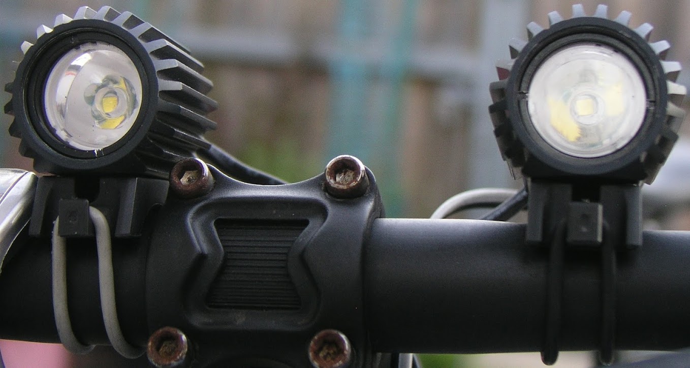
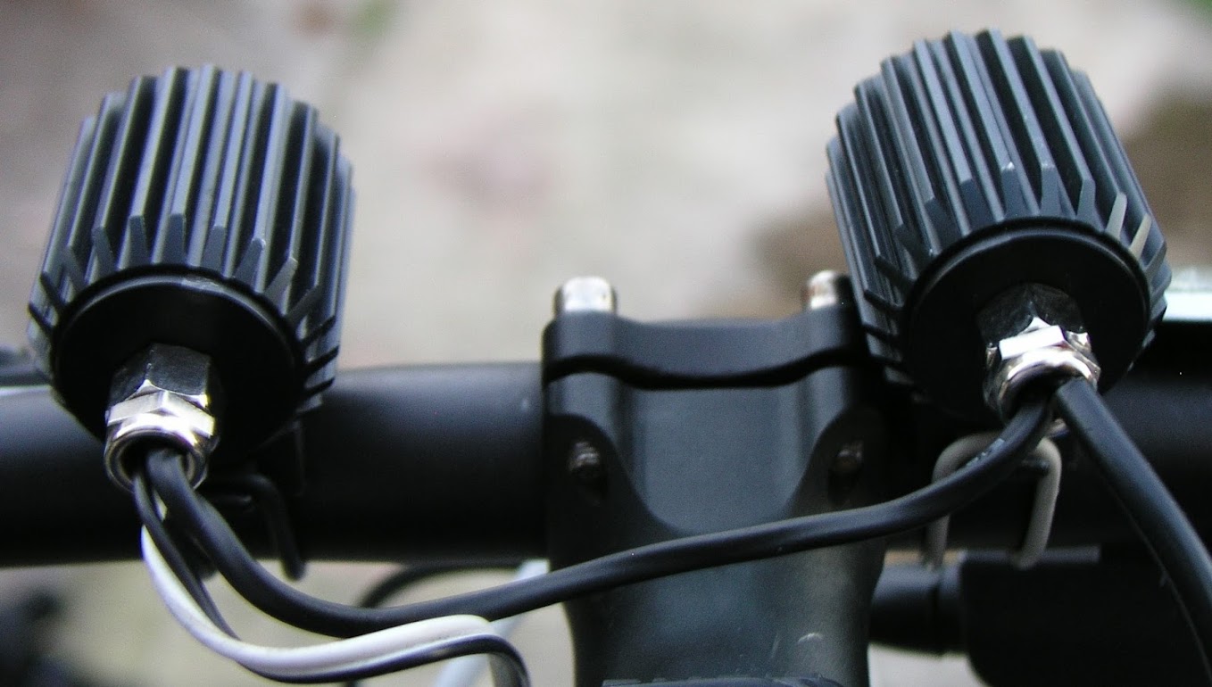
The front lights

2 x easy2led housings, 2 x XM-L. I started with a 30° optic and a 15° optic, but have since switched to using 2 x 10° optics. I used XM-Ls because I had them on hand, but they don’t add anything by way of light at 0.5A over say an XP-G or XP-E2. The main feature of XM-Ls is being able to run at 3A while the rest are out of the game at 1.5A. The XM-L2 however would be a good improvement – an increase in lumens of 25% at 0.5A for the same power.

Image
Image

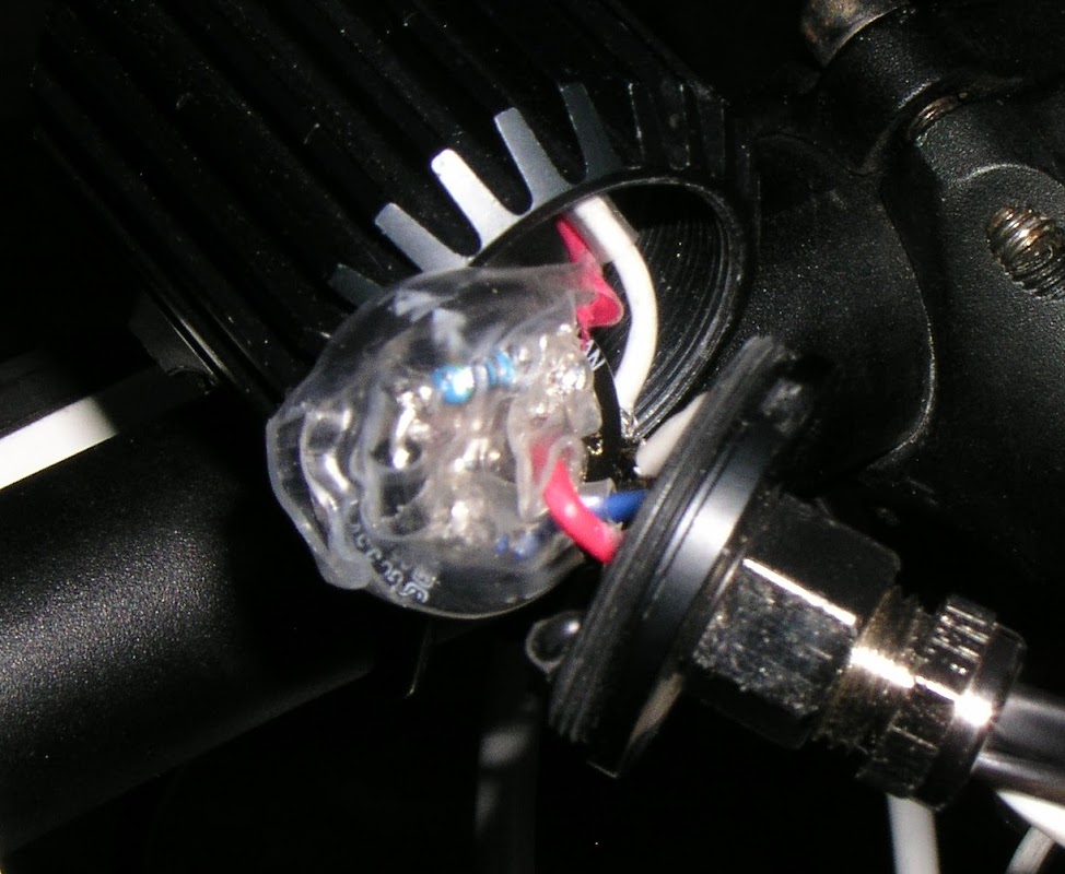
In the back of 1 housing, hidden by the shrink wrap is the super capacitor that powers the standlight (C5), in this case 1.5 farad, a diode (D6) & resistor (R3).
Image

The rear lights

1 x easy2led housing, 2 x XP-E Red, 1 deodorant ball diffuser. In this case the XP-E is the best of the Cree red leds – while an XP-E2 red ultimately produces more lumens, it does so by running up to 1.0A.
As with the front lights, in the back of the housing is a 1.0 farad super cap (C4), a diode (D5) & resistor (R2). To run the standlight circuit, I needed 2 LEDs. To fit 2 red LEDs in 1 easy2led housing, I took some brave pills & then picked up my aviation snips & simply cut off the “excess” aluminium star, making sure I left bits with the traces to the LED, faintly visible in the pic below. The circuit below runs 1 XP-E as a standlight at ~20mA which runs brightly for 4 or 5 minutes before gradually fading away.

ImageImage

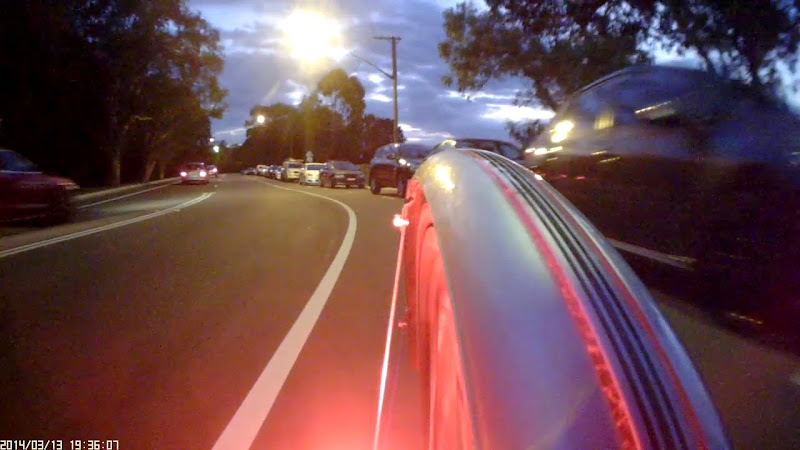
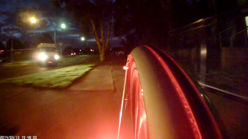
0.5A through two red lights has been described as “crazy bright” & I can happily confirm that is 100% correct. With my deodorant ball diffuser I can tell that the rear is working because of the red glow over the entire rear of the bike. I will see if I can come up with a safe and interesting way to take a picture of the rear light.

The rectifier & other bits

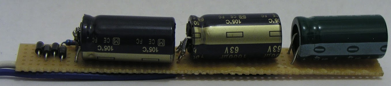
The dynamo output is AC, so you need a rectifier circuit (D1-D4). No printed circuit boards, no surface mount devices for me just simple through hole mounts on a small circuit board including the other bits that don’t fit in the light housings, Capacitors C1-C3, & R1. This time I remembered to take a photo before covering it with shrink wrap :D Once wrapped it is hidden away in the steerer tube.

Image

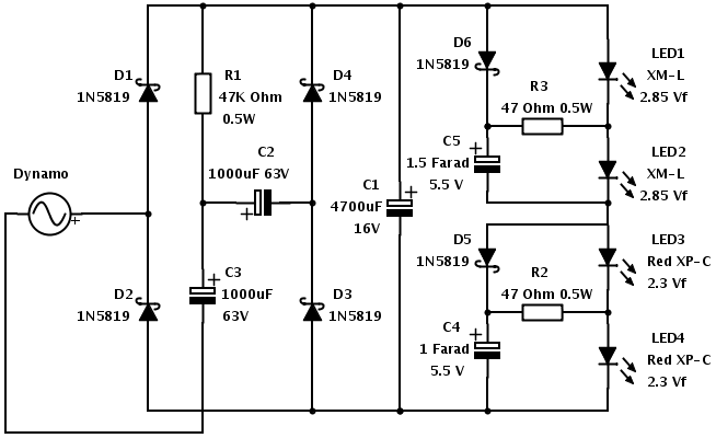
The circuit currently looks like this
Image

The good

I am super happy with the rear light, currently running 2 x red XPEs at 0.5A. Crazy bright when moving & a decent standlight, bright for at least 5 minutes. The front lights put out an acceptable amount of light at the speeds I ride at & the standlight, while not bright enough to ride with, should be enough for visibility when stopped at traffic lights.

To be improved
It would be nice to have more light out front. Putting more LEDs in series though will increase the speed necessary before it produces any light. There is a way around this, but it involves switching, either manually or automatically – eg the Exposure Revo has 4 leds but only 2 light up at low speed. At the rear, 1 LED puts out enough light & would be a small improvement in the low speed performance of the system. I have some ideas on how to make the standlight work, but will need to try them out first.

The real weakness though with DIY lights is the limited available optics. The B&M Luxos and Phillips saferide both use sophisticated reflectors so that oncoming traffic cannot look directly at the LEDs. The reflectors are also shaped to distribute the light on the path ahead. A couple of ideas here involve using a light with good optics such as the Phillips saferide and either replacing the LEDs & electronics or using the light as a ‘dip’ beam with a nice anti-dazzle cut-off and taping into the circuit to power a DIY light for a ‘main’ beam for when no one is in front.

Parts List
The prices are what I paid, as best I can remember, not including postage.
1 SP Dynamo PD-8 AU$120
32 DT Swiss competition spokes AU$34
1 rim I had lying around
3 easy2led housing think I paid $25 each but they are now US$12 ea
2 handlebar clamps US$4
3 Cable glands M8 bag of 5 AU$13.50
1 rear mount – scrounged from the dead lights box
2 XM-L LEDs US$6.39 ea
2 10° optics pack of 5 AU$4.35
2 XP-E red LEDs US$4.20 ea
1 deodorant ball
1 capacitor 4700uF 16V AU$2.50
2 capacitor 1000uF 63V pack of 5 AU$12.15
1 capacitor 1F 5.5V AU$6.20
1 capacitor 1F 5.5V AU$6.95
5 Schottky diodes 1N5819 AU$1.85
1 resistor 47 Ohm pack of 10 AU$0.50
2 resistor 47K Ohm pack of 10 AU$0.50
Anything you can do, I can do slower

User avatar
RideLikeTheWind
Posts: 556
Joined: Wed Oct 10, 2007 4:57 pm
Location: Glenmore Park

Re: DIY Dynamo lights

Postby RideLikeTheWind » Sun Aug 11, 2013 7:20 pm

Awesome work! Detailed explanation too..! If I had a commuter, and not a race bike, I would give this a try just for the kick :)

Thanks for sharing!
Image

warthog1
Posts: 14424
Joined: Wed Jul 25, 2012 4:40 pm
Location: Bendigo

Re: DIY Dynamo lights

Postby warthog1 » Sun Aug 11, 2013 8:43 pm

+1
You are a talented bloke, top stuff :)
Dogs are the best people :wink:

User avatar
find_bruce
Moderator
Moderator
Posts: 10615
Joined: Mon May 09, 2011 8:42 pm
Location: Sydney

Re: DIY Dynamo lights

Postby find_bruce » Mon Aug 12, 2013 3:28 pm

Thanks for the kind words. Warthog I am not that talented - I simply copied the circuit ideas from others. My reason for posting was more to show how simple it can be.
Anything you can do, I can do slower

warthog1
Posts: 14424
Joined: Wed Jul 25, 2012 4:40 pm
Location: Bendigo

Re: DIY Dynamo lights

Postby warthog1 » Mon Aug 12, 2013 6:43 pm

Well looks bloody good to me anyway 8) I wouldn't have had a crack at it, nice work.
Dogs are the best people :wink:

User avatar
rheicel
Posts: 2303
Joined: Sat Jul 14, 2012 5:01 pm
Location: Sydney
Contact:

Re: DIY Dynamo lights

Postby rheicel » Mon Aug 12, 2013 6:48 pm

Very well documented Bruce. Now we need to figure out how to mass produce this prototype, :lol:
Image

}SkOrPn--7
Posts: 2406
Joined: Sun Oct 12, 2008 7:15 pm

Re: DIY Dynamo lights

Postby }SkOrPn--7 » Mon Aug 12, 2013 7:01 pm

Very nice FB and great write up thanks for sharing.

Ricky

wqlava1
Posts: 622
Joined: Sat Mar 14, 2009 8:13 am
Location: Nillumbik, Vic

Re: DIY Dynamo lights

Postby wqlava1 » Tue Aug 13, 2013 7:51 pm

Bruce, I see that you chose front LEDs that are 4300-4500K, as opposed to others available that were up to 7000K. Was that deliberate?

Does anyone have examples of commercial lights that we can compare against that state how soft or harsh their LEDs are?

wqlava1
Posts: 622
Joined: Sat Mar 14, 2009 8:13 am
Location: Nillumbik, Vic

Re: DIY Dynamo lights

Postby wqlava1 » Tue Aug 13, 2013 8:57 pm

Another way of approaching the problem might be to use one of the 2 or 4 cell 18650 lights on this site
http://www.lt-box.com/bike-lights.html? ... rder=price" onclick="window.open(this.href);return false;
which is much cheaper than DX these days, and just insert the part of the circuit to rectify the AC from the dynohub, and maybe the standlight function. You get a good reflector and overall robust head unit (I've bought a few of these for myself and my sons over the last 2 years with no probs). Dunno whether to try this with one of the $25.50 setups with an 8.4V quad battery or the cheaper $16 unit with dual battery which may be half the voltage. I just need to find a male plug that fits and I can start trying it out with one of the 8.4V lights I've got here. Your standlight implementation is very close to the LEDS in the circuit, and these lights have internal circuits to give high/low/blink/off with the click switch on the back, which would require another approach.

User avatar
find_bruce
Moderator
Moderator
Posts: 10615
Joined: Mon May 09, 2011 8:42 pm
Location: Sydney

Re: DIY Dynamo lights

Postby find_bruce » Wed Aug 14, 2013 9:06 am

Thanks RIcky.

You were obviously paying close attention to notice the colour temp of the LEDs wqlava1. Yes it was a deliberate choice, after using a range of lights I found I prefer a neutral or warm white. 3C tint is also good. It is hard to accurately photograph as the white balance of the camera will affect it.

7000k LEDs are too blue for my taste, but they are cheap which is why you will find them on most yum-cha bike lights.

You make an interesting suggestion about using a cheap lighthead. In relation to the 2 or 4 cell driven lights, virtually all the "bike lights" are designed for ~8.4v input & the packs are wired 2S(1, 2 or 3)P. Dynamo lights are more sensitive to beam angle & in my view the battery powered "bike lights" have too much flood. YMMV Reflectors are available but I am not aware of any with a beam angle of 10 degrees

As for your wiring suggestions, I haven't tried it, but here is my guess as to what would happen
  1. the light would flicker at low speed
  2. you would need to be moving faster before you get any useful light
  3. when you slow down or stop the lights would go out - ie no standlight circuit
  4. otherwise it would then work fine until the voltage exceeded the tolerance of the pcb components. At that point things would get very dark very quickly
If you would like an explanation as to why I think these will happen, just ask. I'd be happy to be proven wrong - make sure you take pics along the way & post the results back here :)
Anything you can do, I can do slower

wqlava1
Posts: 622
Joined: Sat Mar 14, 2009 8:13 am
Location: Nillumbik, Vic

Re: DIY Dynamo lights

Postby wqlava1 » Thu Aug 15, 2013 2:58 pm

Bruce,
The first 3 of your list are no great worry for me. i would have to find out how much flicker first, and how much faster before worrying. One of my Supernova E3 Pros has no standlight (capacitor suspected) but still works as a bike light. I've not been particularly inconvenienced by that as it has good optics on the move. More recently i have been using another bike with a Trelock 882 with standlight and it is nice to have, but the 882 is as some have commented in forums a bit tight in the beam and requires you to know the path and not be in an area where you suspect roos might jump out (and we have heaps out only a few km from here).

The fourth point is the key safety item. I like the optics of the cheap front lights, and I think many here would want to use one if the right interface could be provided from a dyno hub, as the cost would be under half the cost of your parts above, albeit with just one pretty good front light. I'd like to know how high the voltage goes with each of my hubs (Son Deluxe, SP SV-8, 2x Shimano Alfine) and then put together a minimal interface. In order to see the voltage it makes sense to have the right load , and your circuit above is straightforward to put together, so I'll do that to support my testing, adding a voltmeter across the output of the bridge and having it next to my GPS on the bars. A 30V digital meter is under $2. I've found some printer power cables on eBay (5 for $5.77) that have the right moulded plug for the lights. Then I can find a few hills to roll down and see how high the voltage goes with each hub, thus knowing the max expected before getting on to some sort of voltage limitation. The highest speed that I usually see is 65 or maybe 70km/h down Marengo near Apollo bay, but I guess that will be enough for most foreseen usage of bikes with hub dynamos.

The key thing that others have not commented on yet much is that you have described a very bright rear light option. In throwaway battery lights there are the planet bike 0.5w and 1W options, and a few others from cateye etc, and in the 18650 lithium batteries there only appears to be the Magicshine MJ-818 for $50 or $60 on DX, with surprisingly no cheaper copies (although there are expensive battery- based solutions from Supernova etc). Magicshine used to have Y-cables to run their front and rear lights off the same 18650 pack. That might be possible together with the cheap front light approach off a dynohub , but still would not have the standlight function that is essential for a rear light. It's not safe to stop on the street in the dark and have nothing to keep a red light on behind you.

User avatar
find_bruce
Moderator
Moderator
Posts: 10615
Joined: Mon May 09, 2011 8:42 pm
Location: Sydney

Re: DIY Dynamo lights

Postby find_bruce » Thu Aug 15, 2013 6:02 pm

There is a slight wrinkle with your proposed test & it goes to the fundamental difference between a dyno and a battery which affects what you need in a circuit.

A dyno is basically a constant current device, but can deliver a surprisingly high voltage - a 3w dyno, despite being referred to as 6V can easily reach 100V in the right circumstances. Back in the dark ages, pre LED, if you got to say something like 30-40 km/h, your dyno would exceed the voltage capacity of the bulb, which would lay down and die. To prevent this, dynos had a zenner diode to limit the voltage. One of the really funky things about an LED is that they are a Light Emitting Diode and the LED actually limits the voltage forward, depending upon the current and the particular LED. A typical XM-L for example is 2.85v at 0.5A. If you are running at 3A however the XM-L 3.35Vf. In my case the voltage of the circuit is (2.85 + 2.85 + 2.3 + 2.3) = ~10.3V. As I start riding the voltage will climb until it hits ~10.3V then it doesn't go any higher, regardless of my speed. My circuit will achieve this voltage at somewhere around 15 km/h.

The entirely different circuit of a battery powered light though does not have a voltage limiter & the higher voltage is highly likely to exceed the capacity of the components. They probably won't die at 8.5V, and it may happen to be higher than 10V, but sooner or later they will turn up their toes and die.

If you have your heart set on modifying an existing light I would get something like a SolarStorm X2, undo the screws on the back to open the light, disconnect the entire circuit board and throw it away. In its place I would put a simple rectifier circuit (D1-D4), and a smoothing capacitor 4700uF 10V, connect it to the dyno & you are good to go. No standlight or tail light, but otherwise ok - 2 LEDs will give you decent low speed performance, the capacitor will all but eliminate the flicker.

I wouldn't do it for the reasons I set out earlier, primarily colour temp & the reflector is far too floody for my taste with the limited current output from a dynamo, but that's the beauty of DIY, you can do it your way.

Do you have a link or item number for the printer power cable ? What is reasonably standard for bike lights is a 5.5 x 2.1mm connector. The most common DC power connectors however are 5.5 x 2.5mm - ie the hole for the internal pin is 0.4mm too big & won't connect. It would be good if you have found an easy alternative to butchering 1m extension cables.
Anything you can do, I can do slower

wqlava1
Posts: 622
Joined: Sat Mar 14, 2009 8:13 am
Location: Nillumbik, Vic

Re: DIY Dynamo lights

Postby wqlava1 » Thu Aug 15, 2013 7:31 pm

Bruce mate,
I am embarrassed (I have forgotten too much since I was taught just over 30 years ago, what your last post explained succinctly). :-)

I'm not so much wanting to mod an existing light for myself as for others, because it would establish a lowest cost bright dynamo powered light. I'll have a shot at it still. For myself, your circuit above.

The printer power cable is actually a 1m extension cable - but at this price there is little regret butchering one end off. .
http://www.ebay.com.au/itm/200817712504 ... 1423.l2649" onclick="window.open(this.href);return false;

wqlava1
Posts: 622
Joined: Sat Mar 14, 2009 8:13 am
Location: Nillumbik, Vic

Re: DIY Dynamo lights

Postby wqlava1 » Thu Aug 15, 2013 11:11 pm

And the 5.5mm x 2.1mm cables are also used by AyUp, except the opposite sex. Chop up 2 cables and run ayUp lights off cheaper 4 cell 18650 packs. Sorry for the diversion.

wqlava1
Posts: 622
Joined: Sat Mar 14, 2009 8:13 am
Location: Nillumbik, Vic

Re: DIY Dynamo lights

Postby wqlava1 » Sat Aug 17, 2013 5:17 pm

OK Bruce, I've ordered enough parts to use the Solarstorm X2 head and your design rear light, with standlight functionality for both.

The Solarstorm head uses XM-L LEDs, so I can change from the LEDs and optics it comes with to a different colour temperature or L2 later once I see what size star or whatever package it uses. There also might be less visible cabling than with 2 separate lights at the front.

It's interesting that the housing supplier that you used from Moscow has just this month listed an M36 housing that takes 35mm triple XM-L optics. But the best cost I can find for the "Ledil cute" optic that they mention is a bit more again than the $25 housing. Maybe later after I poke around a bit more. What would need to change in your circuit to have a 3rd front LED, if it was XM-L or L2?

User avatar
find_bruce
Moderator
Moderator
Posts: 10615
Joined: Mon May 09, 2011 8:42 pm
Location: Sydney

Re: DIY Dynamo lights

Postby find_bruce » Sat Aug 17, 2013 10:44 pm

I'd be interested to see the X2 stripped down & what you end up doing. The Ledil cute optic is available from cutter - $4.95 + shipping.

Going to 3 LEDs up front will change things in a couple of ways - poorer low speed performance meaning you would need to look at voltage doublers or shorting out LEDs at low speed. Of course dropping back to a single rear led would offset that a bit.

The other difference is that the best values of tuning capacitors C2 & C3 depends on the power of the system. Plenty of detail on Martin's website. If you look at the table, you will notice I have used 1000uF 63V, which is listed under 3 LEDs, even though I have 4 LEDs - the is because the total power of my circuit 5.15W is pretty much right on the power value for 3 LEDs - it is an effect of the lower Vf of the XM-L and red XP-E.
Anything you can do, I can do slower

wqlava1
Posts: 622
Joined: Sat Mar 14, 2009 8:13 am
Location: Nillumbik, Vic

Re: DIY Dynamo lights

Postby wqlava1 » Mon Sep 02, 2013 9:48 pm

find_bruce wrote:I'd be interested to see the X2 stripped down & what you end up doing.
Here's some photos of the X2 as it came today with a $30 light and an AyUp for comparison - much smaller than I thought from the pics on lt-box.
Image

It is a bit brighter than the $30 light which is in turn brighter than the AyUps, although the AyUps (with their intermediate optics) have the nicest spread. The $30 Chinese light is very bright in the centre with a loosely defined food around, and the X2 is a bit more spread, which might be enough to see roos. My Trelock 885 dynamo light is too well controlled to avoid glaring oncoming traffic across the top of the beam, and not use up too many photons out to the side - the manufacturer claims it scores 40+ lux but it is most usable in very built up areas with street lights all around rather than the bike paths and country roads that I use at night. These comments on it are from only a short ride on the Diamond Creek Trail (a very twisty mostly unlit bike path) as I want to get on with this.
Image
Image
I pulled the back off the light and there is easy space for the 1.5F 5.5V supercapacitor, which you can see with its legs facing up in the rear housing in one shot. Space around it to put a short piece of heatshrink to insulate it, and still have it move easily. The 2 LEDs each have a red and black wire from the front coming through the heat sink bulkhead. The motherboard goes across the back, strengthened by the daughter board. The blue is soft rubber and the silver is about 16g steel, chromed. I will later measure the depth and width of the step just inside the rear, and the depth down to the bulkhead, when I can get to one of my calipers. I think the most challenge will come from packaging the rest of the circuit, if I just put the front standlight circuit in there. No way will there be space for smoothing and tuning capacitors. I'll have to get the rubber and metal rear cover cut out properly, too. I'm lucky on the one hand that most of my bikes have enough length in the steerer to put a circuit in the way you showed, but most are threaded 1" so I'll have to check the diameter in there.

I pulled a bit of the front off but stopped. The 2 screws hold the metal figure 8 cut out of 16g which presses on the 2 circular glass covers, which rest on soft silicone seals around the front edges of the relatively deep looking optics. Didn't want to go further as the front is OK for now for my purposes, and I might damage it with no spares around.
find_bruce wrote:The other difference is that the best values of tuning capacitors C2 & C3 depends on the power of the system. Plenty of detail on Martin's website. If you look at the table, you will notice I have used 1000uF 63V, which is listed under 3 LEDs, even though I have 4 LEDs - the is because the total power of my circuit 5.15W is pretty much right on the power value for 3 LEDs - it is an effect of the lower Vf of the XM-L and red XP-E.
Yes, these 2 XM-Ls plus a couple of red rear LEDs set up the same as you should be well matched to what is apparently the 5 and a bit watt max power output of the SV-8 hub I plan to use with the light. Ever optimistic, I've ordered the spokes to shift that hub to the bike I use at night on roads around here.

wqlava1
Posts: 622
Joined: Sat Mar 14, 2009 8:13 am
Location: Nillumbik, Vic

Re: DIY Dynamo lights

Postby wqlava1 » Tue Sep 03, 2013 7:52 pm

And here's a link that has pics of a disassembled Solarstorm X2 including the front, and an encouraging comment that it was filled with XM-L2 LEDs, not just XM-L. Hope mine are L2 too.

I've now got all but thermal glue and the red LEDs. I'll start with a wire hanging out of the steerer-based circuit long enough to get to the rear but shorted at the end, and connect it when the front is working and remaining parts arrive.

User avatar
find_bruce
Moderator
Moderator
Posts: 10615
Joined: Mon May 09, 2011 8:42 pm
Location: Sydney

Re: DIY Dynamo lights

Postby find_bruce » Tue Sep 03, 2013 8:29 pm

Sounds good, looking forward to seeing it all come together
Anything you can do, I can do slower

User avatar
find_bruce
Moderator
Moderator
Posts: 10615
Joined: Mon May 09, 2011 8:42 pm
Location: Sydney

Re: DIY Dynamo lights

Postby find_bruce » Sat Sep 28, 2013 8:01 pm

Well it's been a couple of weeks, how is you build coming along he says, tapping his foot impatiently :D
Anything you can do, I can do slower

wqlava1
Posts: 622
Joined: Sat Mar 14, 2009 8:13 am
Location: Nillumbik, Vic

Re: DIY Dynamo lights

Postby wqlava1 » Mon Sep 30, 2013 10:28 pm

find_bruce wrote:Well it's been a couple of weeks, how is your build coming along he says, tapping his foot impatiently :D
Still waiting for the thermal glue for the back light, but tonight I was shoving little components into the corner of some old prototyping board, and I'll try to get to solder them in tomorrow night. That's the part of the circuit that needs to go in the steerer. I'm a bit more constrained than you, as most of my bikes including the one that this will go in are 1" threaded. Looks likely to fit though.

I'm going to be very rough in the back of the Solarstorm, reusing the existing battery wire as it is long enough to get down to the steerer bottom and come back up a couple of inches. I'll leave the clicky switch and the motherboard, both in order to retain physical strength behind the blue silicone, but cut off the daughter board and scrape off the SMDs on the inner side to make space. Retaining the blue silicone hopefully keeps the water proofing. I also hope the wires are red=+ve and black=-ve for the XML LEDs. There must be a way to test non-destructively (he muses hoping for assistance). [ edit - yes there is - too easy!! http://www.allaboutcircuits.com/vol_3/chpt_3/2.html" onclick="window.open(this.href);return false; ]

For future improvements on the Solarstorm X2, there are a number of possibilities. First, they are down to $21 or so at lt-box. Second, there are some double XM-L2s with a screw back. Third, I have found several triple XM-Ls on aliexpress available with similar construction to the Solarstorm X2 with screws front and back, and one quad, all around $50-ish including 4x18650 battery (not that I need any more of those battery packs around here). I like the idea of the multi-LED housings with screws because they have space for at least standlight electronics, because the first step getting inside can be done cleanly, and because they avoid clutter around the bike's central handlebar/stem area. There will always be the questions as to whether the beams are the right shape, but I will worry about that more when I feel I have enough light to need limiting and moulding.

edc1980
Posts: 2
Joined: Sun Nov 17, 2013 5:55 am

Re: DIY Dynamo lights

Postby edc1980 » Sun Nov 17, 2013 6:13 am

Hello all(first post)!


wqlava 1 - did you progress on this project any further? I've just ordered a Solarstorm x2 for exactly this purpose, as I don't want to build a dynamo light from scratch. What did you manage to fit in the light other than the standlight cap? I read on the Pilom dynamo page that if you use a smoothing cap, you should make it inseparable from the LED, as otherwise if disconnected it could store enough charge to fry the LED. Or are you doing without the smoothing cap altogether?

And is the Solarstorm's original switch of any use? I want a switch before the rectifier, but it seems like the Solarstorm's switch is surface mount on the circuit board and a bit more complex than I might understand (I have very little electronics-fu).


find_bruce - great implementation - I especially like the deodorant diffuser! What kind of useable run-time are you getting from the front standlight?

And is there any reason why C1 is so large (4700uF)? If it's not there will I just get flicker (and up to what speed?) without damaging the LEDs?

Thanks in advance - as you can tell, this will be my first semi-DIY dynamo project.

User avatar
find_bruce
Moderator
Moderator
Posts: 10615
Joined: Mon May 09, 2011 8:42 pm
Location: Sydney

Re: DIY Dynamo lights

Postby find_bruce » Fri Mar 14, 2014 1:15 pm

edc1980 wrote:Hello all(first post)!

find_bruce - great implementation - I especially like the deodorant diffuser! What kind of useable run-time are you getting from the front standlight?

And is there any reason why C1 is so large (4700uF)? If it's not there will I just get flicker (and up to what speed?) without damaging the LEDs?

Thanks in advance - as you can tell, this will be my first semi-DIY dynamo project.
Hi edc1980 & I apologise for not replying sooner - I hadn't noticed your questions.
The standlights are giving me good visibility for around 2 minutes & are still visible after 5. You are correct about the size of C1 - the higher the capacitance value of C1, the less flicker & yes you could do without C1 entirely - I am currently working on the Mk 2 build & will probably try that.

Very happy with the visibility of the lights, just a few pics to show off just how effective the rear light is
Image
Image
Image
Anything you can do, I can do slower

kenwstr
Posts: 591
Joined: Tue Apr 23, 2013 8:21 pm

Re: DIY Dynamo lights

Postby kenwstr » Fri Mar 14, 2014 3:59 pm

Just love that ping pong ball tail light diffuser, brilliant.

Ken

User avatar
Aushiker
Posts: 22401
Joined: Tue Jun 05, 2007 1:55 pm
Location: Walyalup land
Contact:

Re: DIY Dynamo lights

Postby Aushiker » Fri Mar 14, 2014 5:05 pm

Love your work Find_Bruce. Always impressed when people do these sorts of things.

Andrew

Who is online

Users browsing this forum: Google [Bot]