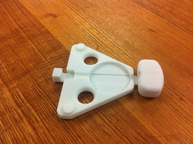
3D Printed Tensiometer

User avatar
boyracer
Posts: 793
Joined: Wed Sep 10, 2008 9:29 pm

Re: 3D Printed Tensiometer

Postby boyracer » Sun Sep 11, 2016 12:13 am

Image
Still waiting on eBay gauges. made 2 so far. one ABS, one PLA.
Another on the way in solid fill, as soon as the students stop using all 3 printers 12 hours a day!

cleaner77
Posts: 1
Joined: Thu Nov 24, 2016 6:10 am

Re: 3D Printed Tensiometer

Postby cleaner77 » Thu Nov 24, 2016 6:24 am

Nice Work, I like it!

Daniel.messem
Posts: 2
Joined: Wed Dec 28, 2016 9:29 pm

Re: 3D Printed Tensiometer

Postby Daniel.messem » Wed Dec 28, 2016 9:57 pm

Very nice

Where would one find the stl files?

User avatar
QuangVuong
Posts: 1794
Joined: Sun Feb 24, 2013 5:04 pm
Location: Villawood, Sydney

Re: 3D Printed Tensiometer

Postby QuangVuong » Thu Dec 29, 2016 12:23 am

What is your email? I will send the files through email for now. I want to finalise the files before uploading them to Thingiverse.
VillaVelo, by the Vuong brothers

Blog: https://villaveloframes.wordpress.com/
FB & IG: @villaveloframes

Daniel.messem
Posts: 2
Joined: Wed Dec 28, 2016 9:29 pm

Re: 3D Printed Tensiometer

Postby Daniel.messem » Thu Dec 29, 2016 12:29 am

QuangVuong wrote:What is your email? I will send the files through email for now. I want to finalise the files before uploading them to Thingiverse.
daniel.messem@gmail.com

much appreciated! :D

User avatar
Warin
Posts: 647
Joined: Sat Sep 01, 2012 5:13 pm

Re: 3D Printed Tensiometer

Postby Warin » Fri Dec 30, 2016 8:30 am

For those of us without 3D printers? :idea: Possibly use some 5 ply and a few bolts.

Possible "improvement" for the 3d printed stuff? Put some metal tubing on the spoke bearing surfaces ... say bit of Al tubing .. would reduce any plastic ware/flex problem on the bearing surfaces? Simply make the plastic the id of the al tubing and add the tubing.

Calibration:
Comparison to another gauge can only be as good as the calibration of the other gauge.

For isolated home use ... I have though of using a spoke and applying tension to it. Tension could be applied as you say directly through weights .... or possibly a balance - use a luggage weighing device on one side (longer length say 900mm long) and the spoken on the other shorter side (say 100mm long). too complex?

Might be easiest to simply stand on a platform with the spoke taking the weight, much simpler. Humm ... Need to think about safety here ... what happens if the spoke snaps or a fitting fails .... you don't want to lose an eye!

The Park tool table shows some variation for spoke diameter/shape, and is why I would favour a method that places a know tension through a sample spoke (where the spoke could be anything you are using, round or aero).

-----------------
On the wheel truing with dial gauges ... been doing this for a while now. Remove the bob on the end of the dial gauge shaft, replace it with some plastic ... I used a bit of kitchen chopping board - cut up it to a 15 mm strip and drill a hole down the centre for a firm fit of the dial gauge shaft. This slides nicely on the bicycle rim without any scratch marks or much noise. For the radial runout I made the plastic into a foot that is wide enough to sit in the outer part of the rim ... even when the rim wobble is extreme this wont interfere with the wheel rotation - aids in measuring rim runout for damaged rims before you start. I like to have a numerical record

Lord Kelvin "I often say that when you can measure what you are speaking about, and express it in numbers, you know something about it; but when you cannot measure it, when you cannot express it in numbers, your knowledge is of a meagre and unsatisfactory kind"

User avatar
QuangVuong
Posts: 1794
Joined: Sun Feb 24, 2013 5:04 pm
Location: Villawood, Sydney

Re: 3D Printed Tensiometer

Postby QuangVuong » Sat Dec 31, 2016 10:15 am

3D printing is a technology that is becoming more widely used and has been approaching the home environment in the past few years. There are plenty of companies who offer 3D printing services, including Officeworks too, as well as MakerLab/FabLab/ThinkSpaces which are places which provide access to these sort of facilities.

The spoke bearing surfaces are only plastic in this version as I planned to make a version that is fully printable, other than the spring and dial indicator. I definitely would swap the spoke bearing surfaces with some bearings. This will minimise the friction on the spoke which may result in an inaccurate measurement as well as greatly improve the longevity of the tool.

The plastic tips for the dial indicators on the truing stand is a good idea. I still haven't gotten around to changing anything on mine.
VillaVelo, by the Vuong brothers

Blog: https://villaveloframes.wordpress.com/
FB & IG: @villaveloframes

User avatar
Warin
Posts: 647
Joined: Sat Sep 01, 2012 5:13 pm

Re: 3D Printed Tensiometer

Postby Warin » Sat Dec 31, 2016 1:14 pm

QuangVuong wrote:The spoke bearing surfaces are only plastic in this version as I planned to make a version that is fully printable, other than the spring and dial indicator. I definitely would swap the spoke bearing surfaces with some bearings. This will minimise the friction on the spoke which may result in an inaccurate measurement as well as greatly improve the longevity of the tool.
Don't think the costs of the bearings are worth it. Friction coefficient of metal to metal are poor so would not introduce much error, any stiction could be reduce by tapping?

In the setup of this you have the 0 setting of the dial gauge, and the determination of the main spring rate, but nothing on the spring preload?
There is also a small correction due to the dial gauge spring rate .. if you use the dial gauge to determine the main spring rate then it may be already compensated for!
Possible Errors (uncertainties)
Length between spoke piviot points (assume force is centered - possibly not much error introduced if not too far off centre)
displacement - from dial gauge
0 setting of dial gauge
spring rate
spring preload
? What have I forgotten ?


Calibration... using tension in a spoke applied by a calculable device.
Think the leaver suits me best - fit it to the underside of a work bench, leaver pivot on a leg, spoke top to work bench top, spoke bottom to leaver, and luggage weight measuring device between leaver and bench bottom. Use a turn buckle to apply adjustable force to the luggage weight measuring device and a few other fittings.

Calibration of the calibrator system
Luggage weight measuring device - simple comparison to other weight measurement devices, or a known mass.
Leaver - distances from pivot to spoke and luggage weight measuring device.
Error compensation - weight of leaver at spoken applies extra tension, measure the weight at this point and use it as an addition to the calculated force.
Possible calibration of calibrator Errors (uncertainties)
Length between pivot points (2 lengths)
forces not being normal to one another (use a level to check that they are normal)
applied force - Luggage weight measuring device
weight of leaver at spoke point
Friction on pivot points - tap .. don't think this will be a problem.
? What have I forgotten ?

Safety of calibration system

What happen if something breaks? :oops:
How much stored energy in the system? Not much - there is little spring energy as while the forces are large the movement is small and most masses are small too.
If the spoke breaks ...
the leaver will move down - possibly a string to restrict downward travel will do here
the spoke will fall ... when you adjust tension you are off to the side - hopefully you will be too far away to suffer much!
if the luggage meter brakes ...
the meter will fall to the ground .. and this would be when your adjusting the tension .. not good. Humm another string to the top of the turn buckle would reduce the possible harm.

User avatar
Warin
Posts: 647
Joined: Sat Sep 01, 2012 5:13 pm

Re: 3D Printed Tensiometer

Postby Warin » Sun Jan 01, 2017 2:07 pm

Another design http://www.ebay.com.au/itm/Icetoolz-Xpe ... xyTjNSewmd

An advantage is that you can get increased resolution on the gauge (e.g. put gauge at top of handle). Another is the sliding friction of the punger is replace by a central pivot where forces will be a higher - so less stiction. Think it is going to be more difficult to 'calibrate' from scratch.

Wiggle has one similar to the Park Tool at $41. http://www.this link is broken.au/lifeline-spoke-tension-meter/

horea
Posts: 1
Joined: Mon Feb 27, 2017 11:21 pm

Re: 3D Printed Tensiometer

Postby horea » Mon Feb 27, 2017 11:29 pm

Hi All,

Has anybody the 3D printing files for the FSA like tensiometer ?

User avatar
QuangVuong
Posts: 1794
Joined: Sun Feb 24, 2013 5:04 pm
Location: Villawood, Sydney

Re: 3D Printed Tensiometer

Postby QuangVuong » Tue Feb 28, 2017 8:28 pm

FSA's tensiometer is made from Jobst Brandt's design. I have his original drawings as well as the files for my one. What are you after the files for, and what is your email?
VillaVelo, by the Vuong brothers

Blog: https://villaveloframes.wordpress.com/
FB & IG: @villaveloframes

catmandu13
Posts: 3
Joined: Wed Mar 29, 2017 7:01 am

Re: 3D Printed Tensiometer

Postby catmandu13 » Wed Mar 29, 2017 7:14 am

I'm having some trouble with the math of this
If the
L=100mm
Spring Rate= 0.66N/mm
N to kgf = 0.101972
And a deflection of 22mm

So then I calculate the Force as Force= 22mm* 0.66N/mm * 0.101972N/kgf to get 1.4806334kgf
Then using the formula (Force * L)/ (4 * D) = T
(1.4806334kgf*100mm)/(4*100mm) = 0.3701583kgf

I see that the spring rate was later determined to be smaller, but the same math still applies, where am i going wrong here?

User avatar
MattyK
Posts: 3257
Joined: Fri Oct 01, 2010 1:07 pm
Location: Melbourne

Re: 3D Printed Tensiometer

Postby MattyK » Wed Mar 29, 2017 9:13 am

FL/4D
where D = deflection, not length...

Also be careful in your assumption about calculating the force.
Pretty much all tension springs will have a preload force that keeps them tight when not under load. That will add to the actual force at 22mm deflection.

catmandu13
Posts: 3
Joined: Wed Mar 29, 2017 7:01 am

Re: 3D Printed Tensiometer

Postby catmandu13 » Thu Mar 30, 2017 12:13 am

Ah yes, I did miss that. However it's still giving me trouble. Every value I use for deflection the tension is equal to 1.682538.
Force = Spring Rate * N to Kgf * Deflection
Force = 0.014806334 = 0.66 * 0.101972 * 0.22
And Tension Kgf = Force * Length / (4 * Deflection)
T=(0.014806334*100)/(4*0.22)

It this case the deflection is canceled out due to the way the force is calculated...I'm I doing that wrong?

T=((0.014806334 = 0.66 * 0.101972 * 0.22)*100)/(4*0.22)

Looking around I for a reference at a beam bending equation website the seems to suggest D from the equation is the section modulus. From what I can tell that's the cross sectional area of the spoke...but I could be wrong on that as well. And didn't make things appear much better when graphed.
ref: http://www.engineersedge.com/beam_bendi ... ding2e.htm

User avatar
MattyK
Posts: 3257
Joined: Fri Oct 01, 2010 1:07 pm
Location: Melbourne

Re: 3D Printed Tensiometer

Postby MattyK » Thu Mar 30, 2017 10:47 am

F = kx
x does not equal D.

It's not a beam bending equation. it's assuming the spoke is totally flexible, like a string. Which is a poor assumption.

<edit> ignore comments about preload - I was thinking of a tension spring.

catmandu13
Posts: 3
Joined: Wed Mar 29, 2017 7:01 am

Re: 3D Printed Tensiometer

Postby catmandu13 » Fri Mar 31, 2017 12:26 am

Ok, think i got it. X is the distance from rest to the spoke position. and F=kx in this application would require knowing the distance from rest to the contact points to calculate the spring displacement, X, and the distance of the top of the dial to the depth of the hole in the handle while at rest to subtract out any preloaded forces?

User avatar
MattyK
Posts: 3257
Joined: Fri Oct 01, 2010 1:07 pm
Location: Melbourne

Re: 3D Printed Tensiometer

Postby MattyK » Fri Mar 31, 2017 11:38 am

X = spring free length minus the length when measuring the spoke tension

User avatar
cmh
Posts: 3
Joined: Sat Apr 07, 2018 1:56 am

Re: 3D Printed Tensiometer

Postby cmh » Sat Apr 07, 2018 6:45 am

I am here specifically for this - I've been working with someone else on Thingiverse to create a 3D printed spoke tensionmeter, and he found this 3D printed tensionmeter by Quang Vuong on photobucket - but I don't see any way to get in touch via Photobucket.

So, I resorted to a web search, and I found this post about a 1995 Slingshot - and that's kinda amazing as I have a 1994 RD4 Slingshot hanging in the shop - funny coincidence!

Anyhow, looks like Quang never uploaded his design to Thingiverse, certainly not that I've seen, so I'm here to ask if he's planning on it, or if I could at least ask for the STL files.

Also - getting in touch with Ric was brilliant - I've worked with Ric, bought an FSA gauge from him and have had it recalibrated by him, but never thought to contact him for the original drawings. Big facepalm moment there when I saw you had just done that.

User avatar
QuangVuong
Posts: 1794
Joined: Sun Feb 24, 2013 5:04 pm
Location: Villawood, Sydney

Re: 3D Printed Tensiometer

Postby QuangVuong » Sat Apr 07, 2018 9:04 pm

Still in development which is why I haven't released finished STLs on Thingyverse. Will join the discussion over on Thingiverse and see where you guys are up to.
Last edited by QuangVuong on Sun Apr 08, 2018 12:35 pm, edited 1 time in total.
VillaVelo, by the Vuong brothers

Blog: https://villaveloframes.wordpress.com/
FB & IG: @villaveloframes

User avatar
cmh
Posts: 3
Joined: Sat Apr 07, 2018 1:56 am

Re: 3D Printed Tensiometer

Postby cmh » Sat Apr 07, 2018 11:19 pm

Awesome!

cip1974
Posts: 1
Joined: Sun Dec 10, 2017 2:04 am

Re: 3D Printed Tensiometer

Postby cip1974 » Tue Aug 25, 2020 7:39 pm

Is it possible to send me the plans please?

Who is online

Users browsing this forum: No registered users