Re: Calibrating your DVRs
Posted: Mon Aug 04, 2014 12:56 pm
Sticky please Mods.
BNA - For the Australian Cycling Community
http://www.bicycles.net.au/forums/
Yep, done.rangersac wrote:Sticky please Mods.
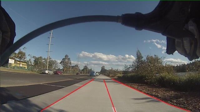
outnabike wrote:OK, so I started a new thread to reply...maestro wrote:My apologies to members for going off topic here I reckon this probably should have its own thread.When doing this you will need to be careful of the lean on your bike [color=#FF0000 wrote:(ideally you should be able to find both ends of your measured line on the photo,[/color] as the line may not be exactly in line with the horizontal axis of the camera). Also, if you are travelling directly in line with the road (parallel to the kerb, not slightly diagonally) then you should be able to draw your centreline of travel with a line from the infinity point to your back wheel. This will need to be done on a per-frame basis as the camera/bike angle is not constant.
So with those assumptions, the car gave more than 1m clearance. If the lane was only 4m wide, then the green lines would be further out and the clearance may have been less than 1 metre.
Apologies if I got over-technical.
Sorry maestro and Oxford I got you both mixed up in my replies before.
Just to address that point maestro, and it is an interesting one. The more I study these grids the more ise the need to look at things from the camera's perspective.
so far I can see we are all a bit right and a bit wrong.
Perspective is in the eye of the beholder. We have to remember that the camera does not take in the view in a three dimensional sense as our eyes do. I did a layout to show the effect of the changing terrain behind the camera, remembering that the cam has been set up on level ground. And that is why the grid appears to dive down into the ground and when lifted (though not very well) in my above pic.
When the police come along and do a reconnaissance of a crash site they are well aware of these anomalies.
I have noted that it important to set the camera p with a mark on the wall for height as well as sideways view. Even without this you can tell how a camera is pointing by the horizon level in the frame.
Here is my grid laid out on level ground but actually lifted to the correct camera eye level about 650mm off the ground.
Your wish to see the finish lines within the camera frame,(if I am getting your drift) can not happen as the periphery of the cameras view with that lens cant accommodate it within the frame and still maintain the grids width. Ok the centre of the grid is 750 mm and if I make that say 1 metre a bit more of the sides of the grid will disappear.
Firstly, yes, I was wrong when I concluded that your camera must have had a narrower field of view, the different grid could be purely because of camera angle.
With regard to your diagramme of the camera view on a hill... A consistent incline would have no affect on the grid lines as the bike angle (and therefore camera angle) would change by the same amount as the road changes. There would be issues with grid lines if the incline was not constant within the field of view (and also where the bike itself is) such as at the top of a crest, or bottom of a dip.
Your question about "finish lines" (I assume that you are referring to the convergence point)... This does not necessarily need to be within the camera field of view. There is space there, irrespective of whether you captured an image of it, and it does not make the theory any less valid if you haven't captured the convergence point in your image. There should be no reason why you cannot add a white area to the top of your frame so that you can draw the converging lines.
As far as raising your grid up to the camera height... Your gridlines will start higher, but must still converge at the same convergence point on the image, so raising the grid plane in space will result in the angles of your 'direction of travel' gridlines getting closer to being horizontal on the image. Now a single line directly out of your camera, parallel to the direction of travel, would go directly out from the lens to the convergence point and would appear as a single dot on the image. If you drew a grid at that height (i.e. the exact height of the camera) then all the lines of the grid would start at the height of the convergence point, and then converge... They would appear on the image as a single horizontal line through the convergence point. Also, a grid at any plane other than the plane of the road is useless as the point where a vehicle's wheels touch the road is really the only point where we can guarantee that we are talking about a point in the same plane as the grid (unless cars come with markings that show the point of the car at exactly your camera level, so we can match them with a grid at that level) so this is probably a moot point anyway.
There is also the issue of lens distortion (is that what you were trying to show with the curved black line in your image above?). You may also be able to calibrate that out with a video of a grid and correct for it using tools such as RawTherapee (if it is found to be significant).
Getting back to stock grids that you calibrate at home and superimpose without further calculations... You need to take into account any change in lean on the bike and change in how the bike sits on the suspension, compared to when the calibration was done, to see if there is any material error in the gridlines (assuming that the camera is mounted to the bike at the same place and angle). If you give up trying to catch drivers only giving you 80cm or more, then you can probably argue convincingly in court (with appropriate calculations addressing error margins due to lean and suspension) that there is 100% certainty that the gap was less than 1 metre.
maestro wrote:outnabike wrote:OK, so I started a new thread to reply...maestro wrote: My apologies to members for going off topic here I reckon this probably should have its own thread.
Sorry maestro and Oxford I got you both mixed up in my replies before.
Just to address that point maestro, and it is an interesting one. The more I study these grids the more ise the need to look at things from the camera's perspective.
so far I can see we are all a bit right and a bit wrong.
Perspective is in the eye of the beholder. We have to remember that the camera does not take in the view in a three dimensional sense as our eyes do. I did a layout to show the effect of the changing terrain behind the camera, remembering that the cam has been set up on level ground. And that is why the grid appears to dive down into the ground and when lifted (though not very well) in my above pic.
When the police come along and do a reconnaissance of a crash site they are well aware of these anomalies.
I have noted that it important to set the camera p with a mark on the wall for height as well as sideways view. Even without this you can tell how a camera is pointing by the horizon level in the frame.
Here is my grid laid out on level ground but actually lifted to the correct camera eye level about 650mm off the ground.
Your wish to see the finish lines within the camera frame,(if I am getting your drift) can not happen as the periphery of the cameras view with that lens cant accommodate it within the frame and still maintain the grids width. Ok the centre of the grid is 750 mm and if I make that say 1 metre a bit more of the sides of the grid will disappear.
Firstly, yes, I was wrong when I concluded that your camera must have had a narrower field of view, the different grid could be purely because of camera angle.
With regard to your diagramme of the camera view on a hill... A consistent incline would have no affect on the grid lines as the bike angle (and therefore camera angle) would change by the same amount as the road changes. There would be issues with grid lines if the incline was not constant within the field of view (and also where the bike itself is) such as at the top of a crest, or bottom of a dip.
Your question about "finish lines" (I assume that you are referring to the convergence point)... This does not necessarily need to be within the camera field of view. There is space there, irrespective of whether you captured an image of it, and it does not make the theory any less valid if you haven't captured the convergence point in your image. There should be no reason why you cannot add a white area to the top of your frame so that you can draw the converging lines.
As far as raising your grid up to the camera height... Your gridlines will start higher, but must still converge at the same convergence point on the image, so raising the grid plane in space will result in the angles of your 'direction of travel' gridlines getting closer to being horizontal on the image. Now a single line directly out of your camera, parallel to the direction of travel, would go directly out from the lens to the convergence point and would appear as a single dot on the image. If you drew a grid at that height (i.e. the exact height of the camera) then all the lines of the grid would start at the height of the convergence point, and then converge... They would appear on the image as a single horizontal line through the convergence point. Also, a grid at any plane other than the plane of the road is useless as the point where a vehicle's wheels touch the road is really the only point where we can guarantee that we are talking about a point in the same plane as the grid (unless cars come with markings that show the point of the car at exactly your camera level, so we can match them with a grid at that level) so this is probably a moot point anyway.
There is also the issue of lens distortion (is that what you were trying to show with the curved black line in your image above?). You may also be able to calibrate that out with a video of a grid and correct for it using tools such as RawTherapee (if it is found to be significant).
Getting back to stock grids that you calibrate at home and superimpose without further calculations... You need to take into account any change in lean on the bike and change in how the bike sits on the suspension, compared to when the calibration was done, to see if there is any material error in the gridlines (assuming that the camera is mounted to the bike at the same place and angle). If you give up trying to catch drivers only giving you 80cm or more, then you can probably argue convincingly in court (with appropriate calculations addressing error margins due to lean and suspension) that there is 100% certainty that the gap was less than 1 metre.
Quite right as the bike is on the same plane, this is what I meant to say.
Lifting the grid on a bike that has the camera pointing down brings it back up to road view but then skews the grid and appears to make it longer. It also places the grid far point out of perspective. But I was just trying to show the effect of a downward facing camera. Doing a grid set out as I have done was for the purpose of getting a positive view of the road width as well as the cars distance.
You can get an idea of your width from the gutter as well.
But it is also to prove whether a camera is aligned correctly in two planes horizontal and vertical.
I suppose a straight line is simpler in the end though as it takes one plane "the vertical" out of concern.
I have not considered suspension at all as I am looking at road bikes, which most commuters would ride. But I know what you mean.Trying to keep it simple.
The horizon point is off because I'm about to crest a hillbychosis wrote:Looks great. the horizon point seems a little off though, it appears to be floating. You could also argue the relevance of the lines that far out. Maybe truncating them at a reasonable distance back would not reduce their effectiveness and remove the floating point
I used GIMP when I put lines on JasonC's image in the moron motorist's thread.Oxford wrote:Yeah, after I posted, I did a quick search and found GIMP, you're right, not too intuitive but exactly what I am after. Just re-layering my pictures now so I can fix up the Google doc.
Yes, it does. The version of PS Elements I've used had layering.outnabike wrote:I have never used Photoshop Elements, which is a lot cheaper. If any one has, does it feature a layering system and working in Photoshop native format?
Microsoft has (had?) one called paint.net which seemed quite reasonable to me when I tried it. Had layers and everything.Oxford wrote:ITW, is there a free or cheap alternative to PhotoShop around? IrfanView can open PSD files but not save to them. I'd like to be able to do layered files, but like many people, not going to buy something like PhotoShop just for this purpose.
Hi Oxford,Oxford wrote:I have a number of complaints with QPS presently using this method/system. QPS requested unedited footage in addition to the overlayed footage for use in court if the matter goes that far. So the answer to your question is YES. I also do not use a form, I use the letter format that I have offered to Cycle. Forms are cold and impersonal and allow little latitude, letters are not, they allow you to convey emotion to let the reader know why the matter you are bringing to their attention is important to you. Forms can be ignored more easily, letters cannot.sumgy wrote:I asked this on SCA's page but it was either missed or ignored.
Has anyone actually taken this method to QLD Police for their assessment of its validity?
It doesn't need to be endorsed as "valid". Its simply an extra tool to assist with showing that a car passed less than 1m. In a court its a combination of your testimony and the camera footage which forms the evidence. If its simply to get police action, it can be useful when writing letters to assistant commissioners, police ministers and your local MP with a please explainsumgy wrote:I asked this on SCA's page but it was either missed or ignored.
Has anyone actually taken this method to QLD Police for their assessment of its validity?


